1 / 3
| General data for R&S®NRP power sensors and accessories | ||
| Temperature | R&S®NRPXXS(N), R&S®NRP18S-10/-20/-25, R&S®NRPXXT(N), R&S®NRPXXA(N), R&S®NRP-ZKx | |
| operating temperature range | 0 °C to +50 °C | |
| permissible temperature range | -10 °C to +55 °C | |
| storage temperature range | -40 °C to +85 °C | |
| R&S®NRP33SN-V/67SN-V | 0 °C to +50 °C | |
| operating temperature range | -10 °C to +60 °C | |
| permissible temperature range | -40 °C to +85 °C | |
| Climatic resistance | damp heat | +25 °C/+55 °C cyclic at 95 % relative humidity with restrictions: noncondensing. in line with EN 60068-2-30 |
| Mechanical resistance | vibration | |
| sinusoidal | 5 Hz to 55 Hz, 0.15 mm amplitude. 1.8 g at 55 Hz, 55 Hz to 150 Hz, 0.5 g constant, in line with EN 60068-2-6 | |
| random | 8 Hz to 650 Hz, 1.9 g (RMS), random in line with EN 60068-2-64 | |
| shock | 45 Hz to 2 kHz, max. 40 g shock spectrum, in line with MIL-STD-810E, method 516.4. procedure I | |
| Altitude | R&S®NRPXXS(N), R&S®NRP18S-10/-20/-25, R&S®NRPXXT(N), R&S®NRPXXA(N), R&S®NRP-ZKx | |
| operating | max. 2000 m | |
| transport | max. 15000 m | |
| Air pressure | R&S®NRP33SN-V/67SN-V | |
| operating 32 | 0 hPa to 1060 hPa | |
| transport | 0 hPa to 1060 hPa | |
| Electromagnetic compatibility | EU: in line with EMC Directive 2014/30/EU | applied harmonized standards: EN 61326-1 (industrial environment) EN 55011 (class B) |
| RoHS | EU: in line with Directive 2011/65/EU on the restriction of the use of certain hazardous substances in electrical and electronic equipment | applied harmonized standard: EN IEC 63000 |
| Calibration interval | recommended | 2 years |
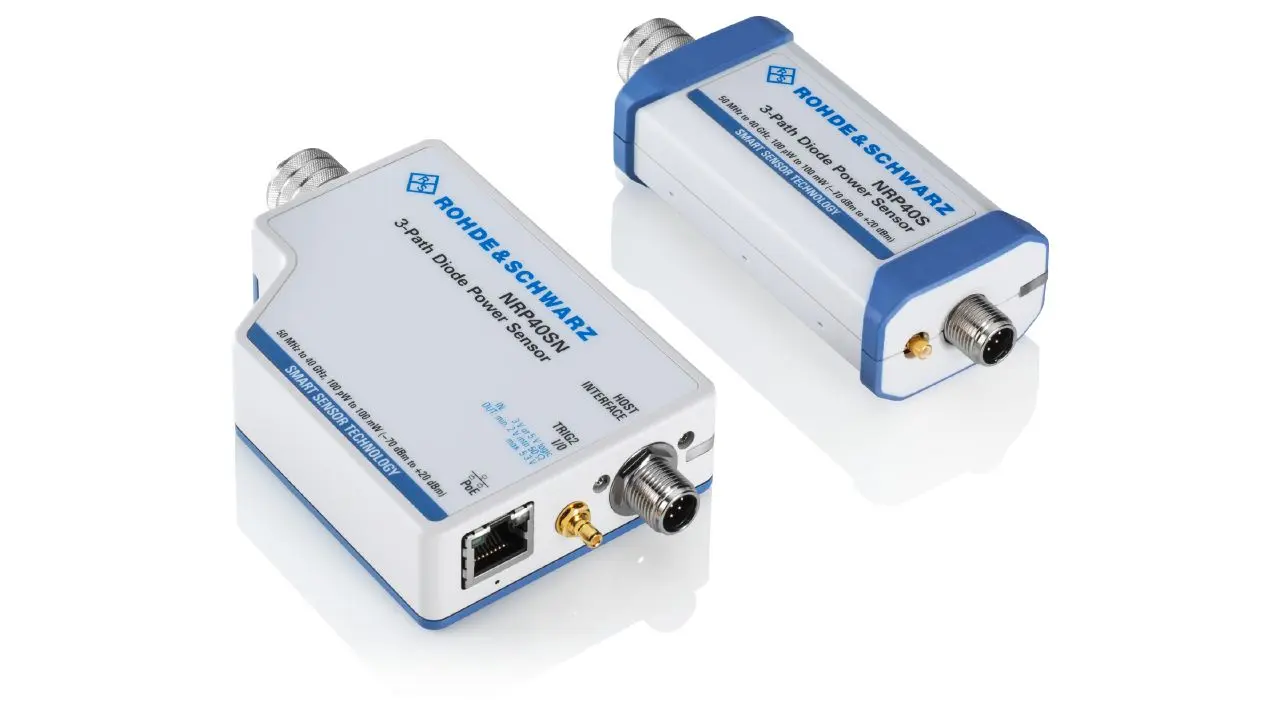
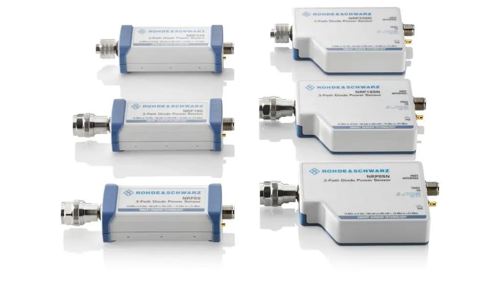
| Models | Frequency range | Level range | LAN interface | Connector type |
|---|---|---|---|---|
| R&S®NRP8S | 10 MHz - 8 GHz | -70 dBm - +23 dBm | N (m) | |
| R&S®NRP8SN | 10 MHz - 8 GHz | -70 dBm - +23 dBm | ● | N (m) |
| R&S®NRP18S | 10 MHz - 18 GHz | -70 dBm - +23 dBm | N (m) | |
| R&S®NRP18SN | 10 MHz - 18 GHz | -70 dBm - +23 dBm | ● | N (m) |
| R&S®NRP33S | 10 MHz - 33 GHz | -70 dBm - +23 dBm | 3.5 mm (m) | |
| R&S®NRP33SN | 10 MHz - 33 GHz | -70 dBm - +23 dBm | ● | 3.5 mm (m) |
| R&S®NRP40S | 50 MHz - 40 GHz | -70 dBm - +20 dBm | 2.92 mm (m) | |
| R&S®NRP50S | 50 MHz - 50 GHz | -70 dBm - +20 dBm | 2.4 mm (m) | |
| R&S®NRP50SN | 50 MHz - 50 GHz | -70 dBm - +20 dBm | ● | 2.4 mm (m) |
| R&S®NRP67S | 50 MHz - 67 GHz | -70 dBm - +20 dBm | 1.85 mm (m) | |
| R&S®NRP67SN | 50 MHz - 67 GHz | -70 dBm - +20 dBm | ● | 1.85 mm (m) |
| R&S®NRP18S-10 | 10 MHz - 18 GHz | -60 dBm - +33 dBm | N (m) | |
| R&S®NRP18S-20 | 10 MHz - 18 GHz | -50 dBm - +42 dBm | N (m) | |
| R&S®NRP18S-25 | 10 MHz - 18 GHz | -45 dBm - +45 dBm | N (m) | |
| R&S®NRP90S | 50 MHz - 90 GHz | -70 dBm - +20 dBm | 1.35 mm (m) | |
| WR 12 via | ||||
| WCA12 - 135 | ||||
| R&S®NRP90S | 50 MHz - 90 GHz | -70 dBm - +20 dBm | 1.00 mm (m) | |
| R&S®NRP90SN | 50 MHz - 90 GHz | -70 dBm - +20 dBm | ● | 1.35 mm (m) |
| WR 12 via | ||||
| WCA12 - 135 | ||||
| R&S®NRP33SN-V | 10 MHz - 33 GHz | -70 dBm - +23 dBm | ● | 3.5 mm (m) |
| R&S®NRP67SN-V | 50 MHz - 67 GHz | -70 dBm - +20 dBm | ● | 1.85 mm (m) |
| Parameter | Sensor Model | Value |
|---|---|---|
| Dimensions (W*H*L) | R&S®NRPXXS | 48mm * 30mm * 138 mm(1.89 in * 1.18 in * 5.43 in) |
| R&S®NRPxxSN, R&S®NRP33SN-V/67SN-V | 73mm * 26 mm * 146 mm(2.87 in * 1.02 in * 5.75 in) | |
| R&S®NRP18S-10 | 48mm * 30 mm * 184 mm(1.89 in * 1.18 in * 7.25 in) | |
| R&S®NRP18S-20 | 53 mm * 46 mm *252 mm(2.09 in * 1.82 in * 9.93 in) | |
| R&S®NRP18S-25 | 53 mm * 46 mm * 310 mm(2.09 in * 1.82 in * 12.21 in) | |
| Weight | R&S®NRPXXS | < 0.20 kg (0.44 lb) |
| R&S®NRPxxSN, R&S®NRP33SN-V/67SN-V | <0.35 kg (0.77 lb) | |
| R&S®NRP18S-10 | <0.27 kg (0.59 lb) | |
| R&S®NRP18S-20 | <0.37 kg (0.81 lb) | |
| R&S®NRP18S-25 | < 0.47 kg (1.02 lb) |