What Are Insulation Testers and Which Type Is Best?

Time:2026-09-17 Author:Madeline
0%

Insulation Testers are essential instruments for checking whether electrical insulation can safely withstand voltage without allowing dangerous leakage. They help technicians assess cables, motors, transformers, switchgear, and other equipment before failure appears. A healthy reading is reassuring, but it is not a permanent guarantee. Temperature, humidity, contamination, aging, and mechanical damage can change the result.

Electrical safety expert Jim White has stated, “There are no shortcuts to electrical safety.” That principle explains why choosing an Insulation Tester requires more than comparing prices or maximum test voltage. A basic megohmmeter may suit routine cable checks and small maintenance tasks. A digital insulation resistance tester can offer clearer readings, timed tests, automatic discharge, and data storage. Advanced models may include polarization index, dielectric absorption ratio, ramp testing, and diagnostic analysis.

The best type depends on the asset, voltage class, work environment, and required evidence. A 500-volt tester may be suitable for many low-voltage circuits, while larger motors and industrial systems can require 1,000, 2,500, or 5,000 volts. Higher voltage is not automatically better. It can produce misleading results or stress equipment when applied without proper guidance.

Field experience also exposes an uncomfortable detail: technicians sometimes trust one impressive number too quickly. Test leads may be dirty. The surface may be wet. The equipment may not be fully isolated. A careful outline should therefore explain tester types, test voltage selection, safety procedures, result interpretation, and measurement limitations. The right instrument is the one that produces dependable information without creating unnecessary risk.
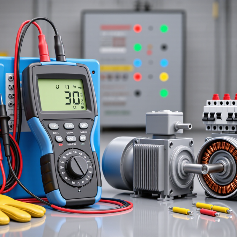
What Are Insulation Testers and Which Type Is Best?

Insulation Testers: Purpose, 250–1,000 V Test Ranges, and IEC 61557-2

Insulation testers, often called megohmmeters, check whether electrical insulation keeps current on its intended path. They apply a controlled DC voltage and measure resistance in megohms. A weak result may reveal moisture, crushed cable insulation, contamination, or aging inside a motor winding. In practical field testing, 250 V often suits sensitive control circuits, while 500 V is common for low-voltage wiring. A 1,000 V setting may suit heavier cables or equipment, but only when the manufacturer’s instructions permit it.

The selected voltage matters. Too little may miss a developing fault. Too much may stress components that were never designed for that test. IEC 61557-2 specifies performance requirements for insulation resistance measuring equipment used on low-voltage systems. It addresses measurement reliability and essential safety functions. However, compliance does not make every test automatically safe. The circuit must be isolated, verified dead, and discharged after testing. A single good reading can still mislead, especially when moisture changes during the day.

Tips: Test phase-to-earth and, where appropriate, phase-to-phase. Record temperature, humidity, test voltage, and resistance. Compare results with previous readings instead of relying on one pass-or-fail number. Keep test leads clean and inspect their insulation before use. Never touch the circuit during testing or immediately afterward. Some devices retain charge. This detail is easy to underestimate. A careful tester also pauses when results seem unusual, checks the connection, and repeats the measurement under controlled conditions.

How Insulation Resistance Testing Works: DC Voltage, Leakage Current, and MΩ

An insulation tester checks whether electrical insulation is keeping current where it belongs. During testing, the instrument applies a controlled DC voltage between conductors and earth, or between separate conductors. This voltage stresses the insulation without supplying normal operating power. A sound insulation system allows only a very small leakage current.

The tester measures that leakage current and calculates resistance with the relationship R = V/I. The result usually appears in megohms, or MΩ. Higher resistance generally indicates better insulation. Moisture, dust, heat, and aging can lower the reading. Cable length also matters because long cables create more capacitance and may need extra charging time. Wait for the value to stabilize.

Testing is not just pressing a button. Isolate the circuit, verify it is de-energized, and connect the leads securely. After the test, allow the equipment to discharge before touching it. A low reading may indicate damaged insulation, but a changing reading can reflect surface contamination or stored charge. I have found that rushing this step produces misleading results. The meter is not infallible. Compare readings with earlier records, equipment specifications, and safe maintenance limits. The best tester type depends on the system’s voltage, test range, automatic discharge features, and the technician’s ability to interpret changing MΩ values.

Analog, Digital, and Multifunction Testers: Accuracy, Safety, and CAT Ratings

Insulation testers apply a controlled DC voltage to reveal damaged insulation, moisture, and leakage paths. Analog models show resistance through a moving needle. They remain useful when gloves, dust, or bright sunlight make screens difficult to read. However, readings can be harder to record accurately. Digital testers provide clearer values, automatic discharge, and steadier results. Their convenience can still encourage careless testing.

Accuracy depends on method, not only resolution. IEC 61557-2 specifies performance requirements for insulation resistance measurement equipment. Select test voltages that match the circuit, such as 250, 500, or 1,000 volts. A 2023 NFPA report found electrical distribution and lighting equipment involved in 24% of non-home structure fires from 2016–2020. That figure supports disciplined maintenance, but it does not make every fault visible. Cable temperature, surface contamination, and test duration can change readings. I have seen a “good” result become questionable after cleaning a damp terminal.

Tips: Choose a tester with a CAT rating suitable for the installation. CAT III fits distribution circuits, while CAT IV suits service entrances and outdoor supply points. Confirm the rating includes the required voltage. Disconnect sensitive electronics before testing. Verify zero voltage, test with controlled leads, and allow automatic discharge afterward. Multifunction testers add continuity, loop, and RCD checks, saving time during inspections. Yet more functions can create more setup errors. Record test voltage, temperature, and resistance, not just the final number.

Insulation testers are available in analog, digital, and multifunction formats. The chart compares representative test-voltage configurations and common safety-category options. These values describe typical instrument configurations rather than every model; always verify the instrument’s datasheet, IEC 61010 CAT rating, and IEC 61557-2 insulation-resistance requirements before testing.

Choosing Test Voltage: 250 V, 500 V, 1,000 V, or 2,500 V Applications

Insulation testers apply controlled DC voltage to reveal leakage through damaged, damp, or aging insulation. The selected voltage matters more than many technicians expect. Too little may miss weakness; too much may stress fragile components.

A 250 V test suits control circuits, sensors, and low-voltage electronics that could contain surge protection. A 500 V test is widely used for cables, panels, and equipment rated up to 500 V.

IEC 61557-2:2019 defines performance requirements for insulation resistance testers, while IEEE 43-2013 uses a one-minute insulation-resistance reading for rotating machines. That timing matters. A quick reading can hide absorption effects.

Use 1,000 V for industrial motors, generators, and longer cable runs when the equipment rating and maintenance procedure permit it. For medium-voltage equipment, 2,500 V may be appropriate, but only with the manufacturer’s procedure, discharge controls, and documented isolation. NETA testing guidance also links test voltage to equipment class, not personal preference. A higher number is not automatically better.

In practice, record temperature, humidity, test duration, and the final resistance. IEC guidance commonly supports polarization-index assessment through 10-minute and one-minute readings. Yet PI can mislead on small or heavily contaminated systems. I have seen a clean result change after moisture entered a junction box. The instrument was correct. The test conditions were incomplete. For safety, discharge the circuit fully after every test.

PI and DAR Diagnostics: IEEE 43’s 1-Minute and 10-Minute Measurements

Insulation testers apply controlled DC voltage and track resistance as insulation charges. The meaningful evidence appears over time. IEEE Std 43-2013 specifies readings at one minute and ten minutes for Polarization Index testing. PI equals R10min divided by R1min. A rising value usually indicates healthy polarization, while a flat curve may suggest moisture, contamination, or aging insulation.

Shorter tests still have value. DAR commonly compares resistance at 60 seconds with resistance at 30 seconds. It provides a quick screening result before a longer PI test. However, DAR and PI are not interchangeable. IEEE 43 emphasizes temperature correction, winding temperature, test voltage, and machine history. A ratio without those details can mislead. Very easily.

The U.S. Department of Energy’s U.S. Industrial and Commercial Motor System Market Assessment estimates motor systems consume about 68% of industrial electricity. Reliable insulation testing therefore protects more than one motor. It supports decisions across large operating assets. In practical maintenance, record the ambient temperature, surface condition, test voltage, and exact timestamps. Compare today’s curve with previous records, not only a pass-or-fail number. A high PI does not erase a damaged lead or a wet terminal box. That is the uncomfortable part. Field judgment still matters.

What Are Insulation Testers and Which Type Is Best? — PI and DAR Diagnostics: IEEE 43’s 1-Minute and 10-Minute Measurements
Test or Instrument What It Measures Typical Test Duration Calculation or Output Common Diagnostic Use Important Interpretation Notes
Insulation Resistance (IR) Tester DC resistance between a winding or conductor and ground, or between isolated windings. Usually 1 minute for a standard spot reading; longer tests may be used for polarization diagnostics. Resistance reported in MΩ, GΩ, or TΩ at a selected DC test voltage. Detects moisture, contamination, surface leakage, damaged insulation, and gross insulation deterioration. The reading is affected by temperature, humidity, winding capacitance, test voltage, and surface cleanliness. Record temperature and conditions with every result.
Spot Insulation-Resistance Test Insulation resistance after a fixed application of DC voltage, commonly measured at the 60-second point. 1 minute IR60s = resistance measured at 60 seconds. Quick acceptance checks, maintenance trending, and comparison with previous results. A single value is less informative than a temperature-corrected trend. A declining trend may indicate contamination, moisture, or aging.
Polarization Index (PI) The change in insulation resistance over a ten-minute DC test period. 10 minutes PI = IR10 min ÷ IR1 min Evaluates absorption behavior and helps identify moisture or contamination in many rotating-machine windings. IEEE 43 commonly uses a 10-minute-to-1-minute ratio. A PI of about 2.0 or higher is often treated as a favorable general indication, but limits depend on equipment design, insulation system, temperature, and historical data.
Dielectric Absorption Ratio (DAR) The increase in insulation resistance during the early part of a DC test. Commonly 60 seconds, with an early reference reading at 30 seconds. DAR = IR60s ÷ IR30s Provides a faster indication of moisture, contamination, and dielectric absorption when a full PI test is impractical. DAR is a field diagnostic ratio and is not the 10-minute PI measurement specified for IEEE 43 PI testing. Interpretation should follow the equipment manufacturer’s procedure or site standard.
High-Voltage IR Tester Insulation resistance using a controlled DC test voltage suitable for medium- or high-voltage equipment. Usually 1 minute for IR; 10 minutes for PI when applicable. DC test voltage may range from hundreds of volts to several kilovolts, with resistance and leakage-current readings. Testing motors, generators, transformers, cables, switchgear, and other electrical insulation systems. The test voltage must be appropriate for the equipment rating and procedure. Disconnect sensitive electronic devices and fully discharge the equipment after testing.
Low-Voltage IR Tester Insulation resistance on low-voltage circuits and equipment. Commonly 1 minute or less for routine checks. Resistance typically displayed in MΩ or GΩ at a lower selectable DC voltage. Control wiring, appliances, low-voltage motors, distribution circuits, and preliminary troubleshooting. A lower test voltage reduces stress on connected equipment but may not reveal defects that require a higher diagnostic voltage. Follow the equipment-specific procedure.
IEEE 43 Test-Voltage Selection Recommended DC test-voltage ranges for rotating-machine windings based on winding rated voltage. Applied for the selected test period, commonly 1 minute for IR or 10 minutes for PI. Up to 1,000 V winding: 500 V DC
1,001–2,500 V: 500–1,000 V DC
2,501–5,000 V: 1,000–2,500 V DC
5,001–12,000 V: 2,500–5,000 V DC
Above 12,000 V: 5,000–10,000 V DC
Helps select a suitable DC test voltage for rotating-machine insulation testing. These ranges should be applied with the complete standard, equipment documentation, safety rules, and site procedures. Do not select a test voltage solely from a table without verifying the equipment condition.
Temperature-Corrected IR Insulation resistance normalized to a reference temperature for comparison. Measured during the IR, DAR, or PI test. Temperature correction is applied according to the applicable standard or established equipment procedure. Trend analysis and comparison of measurements taken at different ambient or winding temperatures. Insulation resistance generally decreases as temperature rises. Comparing uncorrected readings taken at different temperatures can lead to incorrect conclusions.
Best Choice for Routine Maintenance A tester with selectable DC voltage, timed IR readings, DAR and PI calculation, temperature recording, and discharge capability. 1-minute IR, approximately 1-minute DAR, and 10-minute PI when required. IR60s, DAR, PI, test voltage, leakage current, temperature, and time-stamped results. Maintenance programs that require repeatable measurements, automated ratios, and historical trending. The “best” tester is determined by the equipment voltage class, required standards, test environment, safety features, and data-recording needs—not by maximum test voltage alone.
Safety note: Insulation tests apply potentially hazardous DC voltage. Isolate the equipment, verify the absence of voltage, use appropriate personal protective equipment, keep unauthorized personnel clear, and discharge and ground the test object after testing. The values shown are general diagnostic guidance; the applicable standard, equipment documentation, and site safety procedure take precedence.

FAQS

What does an insulation resistance test measure?

It checks whether insulation keeps current between conductors and earth. A sound system allows very little leakage current. The result appears in megohms, or MΩ.

How does the tester calculate resistance?

The instrument applies controlled DC voltage and measures leakage current. Resistance follows R = V/I. Higher resistance usually suggests healthier insulation.

Why can insulation resistance readings become low?

Moisture, dust, heat, and aging can weaken insulation performance. A wet terminal box may produce a disappointing reading. Cable length also affects charging time.

Why should the reading stabilize before recording it?

Long cables create capacitance and need additional charging time. Record the value after it becomes reasonably stable. A rushed reading can mislead.

What safety steps are needed before testing?

Isolate the circuit and verify it is de-energized. Connect the test leads securely. After testing, let the equipment discharge fully. Do not touch it too soon.

What do PI and DAR tests show?

PI compares resistance after ten minutes with resistance after one minute. DAR commonly compares sixty seconds with thirty seconds. PI gives a longer diagnostic trend. DAR is a quicker screening check.

What does a rising resistance curve usually indicate?

A rising value often suggests healthy insulation polarization. A flat curve may indicate moisture, contamination, or aging. The curve matters. One number is not enough.

Which details should be recorded with each test?

Record temperature, surface condition, test voltage, and exact timestamps. Compare the new curve with earlier records. A high PI cannot excuse a damaged lead. Field judgment remains imperfect, but necessary.

Conclusion

Insulation Testers are specialized instruments used to evaluate the condition of electrical insulation by applying a controlled DC voltage and measuring leakage current. The result is expressed as insulation resistance in megohms (MΩ), helping identify moisture, contamination, aging, or damage in cables, motors, panels, and other electrical systems. The article explains common test ranges from 250 V to 1,000 V, as well as higher-voltage applications up to 2,500 V, while highlighting the safety principles and measurement requirements associated with IEC 61557-2.

It also compares analog, digital, and multifunction testers in terms of accuracy, usability, protection, and CAT ratings. Selecting the correct test voltage depends on the equipment’s operating voltage, insulation type, and applicable procedures. For deeper diagnostics, Polarization Index (PI) and Dielectric Absorption Ratio (DAR) tests track resistance over time. In particular, IEEE 43-based testing commonly compares one-minute and ten-minute readings to assess insulation polarization and identify potential deterioration.


Madeline

Madeline

Madeline is a dedicated marketing professional with a wealth of expertise in our company's core offerings. With a keen understanding of the industry, she brings a unique perspective to her role, consistently delivering high-quality content that highlights the superior aspects of our products. As......